How to Create a Wall with Variable Thickness in Revit
When an as-built wall differs from the design dimensions, you may need to record its exact measured width at both ends. Revit can represent this variable thickness by joining two non-parallel walls.
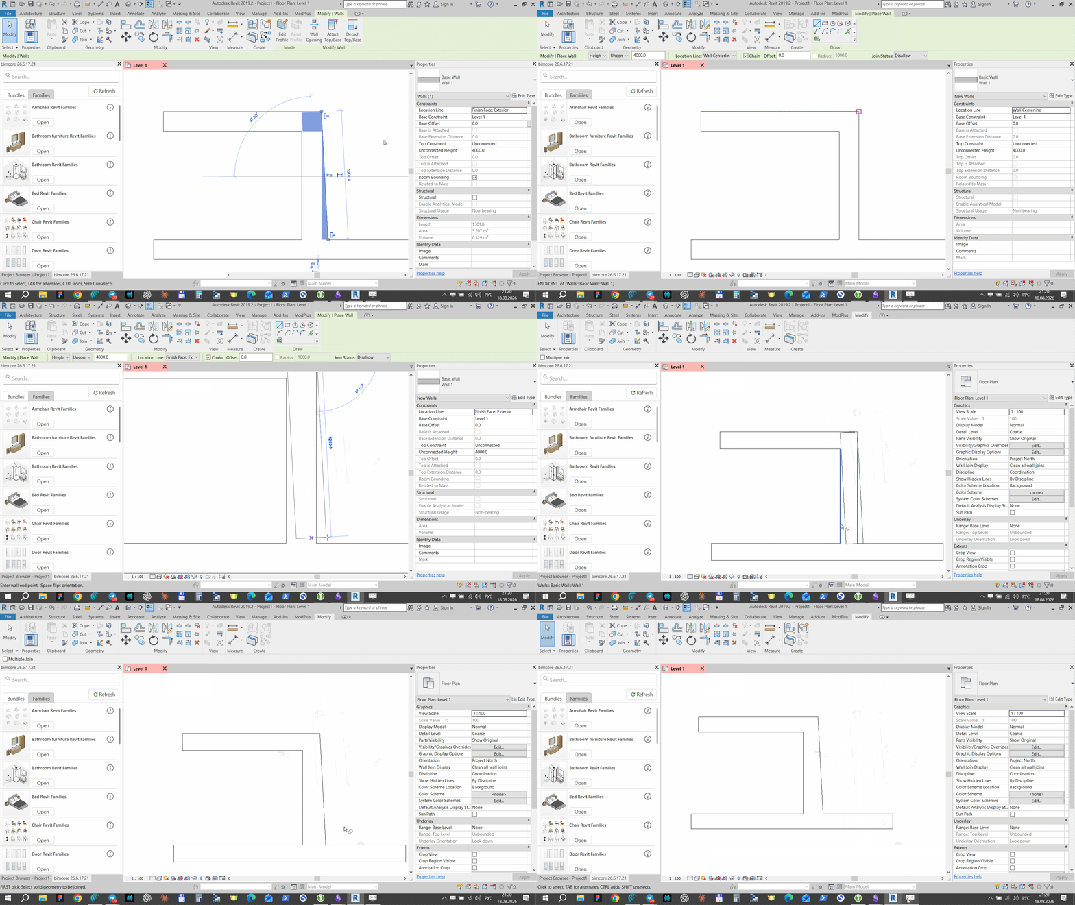
1. Join two non-parallel walls
This is the simplest and most practical method for this task.
- Create the first wall with a constant thickness.
- Start the Wall tool for the second wall.
- Set Location Line to Finish Face: Exterior or Finish Face: Interior. Choose the face that must remain fixed.
- Place the first point exactly at the corner where the original thickness must be preserved.
- Draw the second wall toward the end where the combined wall needs to become thicker.
The first point must snap to the corner. Otherwise, the specified thickness at that end will change. Press Spacebar while drawing if the second wall appears on the wrong side of the location line.
The Location Line controls which face stays on the path you draw. Autodesk explains the available options in About the Wall Location Line.
After both walls are in place:
- Open the Modify tab.
- Choose Join Geometry.
- Join the intersecting walls until no separating line remains.
The two walls now read as one wall with a different thickness at each end.
If the joint line remains visible, see how to remove the joint line between walls.
2. Create a wall as a Model In-Place element
You can also create the required shape with Model In-Place, but this is a poor choice for a wall. The element is not created with Revit's native Wall tool, so many standard wall properties and behaviors are missing. This makes the element harder to edit and use later in the project.
Just starting out?
You don't have to learn Revit alone. Join the BIMCORE community — ask questions, get answers from real Revit users, and download free families to practice with.
Join the Community →